

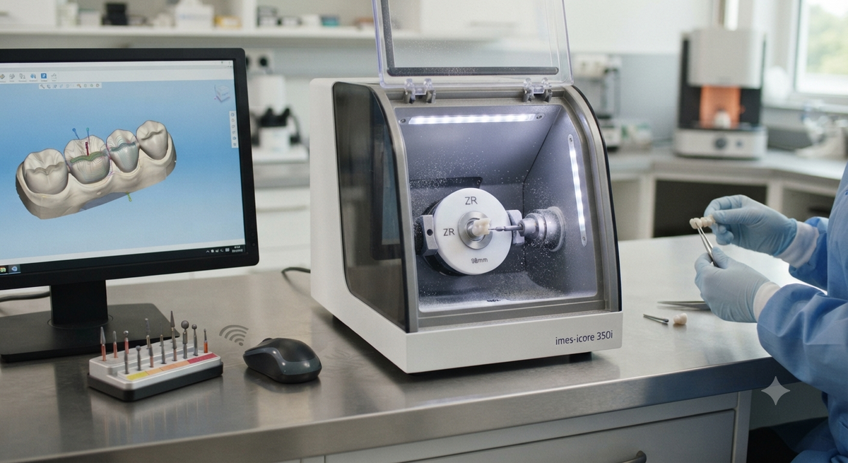
A smooth zirconia workflow feels almost boring: the case goes in, the crown comes out, and it fits. Getting there takes a few habits that are easy to adopt and easy to forget. Whether you run a small in-house lab or a busy production floor, this guide covers how to set up your Aidite CAD CAM workflow, choose tools and avoid the errors behind most remakes.
Mapping the Digital Workflow End to End
Think of the process as a chain: scan, design, nesting, milling, sintering and finishing. A weak link anywhere shows up at the end. The most helpful step is to write your chain down, with the person responsible and the settings used at each stage. When something goes wrong, you can trace it instead of guessing. That applies to every Aidite CAD CAM job, whether it is a single crown or a bridge. Even a one-page flowchart pinned near the mill is enough to keep everyone aligned.
Choosing the Right Tools for Zirconia
Your tool list includes the mill, the CAM software, the burs, the furnace and the material. They should be chosen to work together. Check that your CAM library supports the discs you plan to use, that the burs are validated for your machine, and that the furnace can run the programs the manufacturer recommends. If you work with several brands such as Upcera zirconia, make sure each disc's data is loaded correctly, since mismatched data leads to size errors.
Nesting and Sprue Strategy
Nesting means placing restorations within the disc so they can be cut safely. Keep units away from the disc's outer edge, avoid placing thin parts where the bur must reach awkwardly, and position restorations so the sprue attaches to a non-critical area. For multilayer discs, nest according to where you want the gradient to fall.
Connectors on bridges should be strong enough to survive milling. A sprue that is too thin can break during cutting, while one that is too thick leaves a mark that takes longer to finish.
Where Milling Errors Usually Begin
Most problems come from a short list of causes. Here is what to check first:
• Wrong shrinkage data: entering the wrong disc batch information can make every crown too large or small.
• Worn or unmatched burs: these cause rough margins and chipped edges.
• Loose disc or dirty holder: a disc that does not sit true leads to uneven cuts.
• Rushed toolpaths: speed saved on the mill is often lost in rework.
Fit complaints are often blamed on the scan or design, but a check of the data entered into the CAM software and the condition of the mill usually finds the answer faster.
Quality Checks Between Each Stage
Do not wait until the crown is finished to look for problems. After design, check thickness and contacts on screen. After milling, inspect margins and the surface before sintering, since a flawed crown is cheaper to remake at this stage. After sintering, try it on the model and compare it with the design. A short checklist at each point takes a minute and prevents wasted furnace cycles.
Calibration and Maintenance Habits That Pay Off
Schedule routine calibration according to the machine maker's instructions, and keep the spindle, collet and dust extraction clean. A mill that is cleaned on a schedule needs fewer surprise repairs. Record every calibration, bur change and material batch, so you can link a change in results to a change in routine.
Building One Standard Routine for Your Team
A workflow works best when everyone follows the same steps. Write your settings and checks in a short guide, train new team members on it, and review it when you change materials or machines. When two technicians do the same task two different ways, results vary, and the cause becomes hard to find. A single documented routine keeps quality steady and makes training easier.
Bringing Your Blocks and Process Together
Consistent material makes everything above easier. Working with a dependable zirconia blocks supplier USA labs rely on means each batch behaves like the last, which gives you the predictability a digital workflow depends on. Pair that with a documented routine for nesting, milling and sintering, and you will see fewer remakes and steadier turnaround.
A well-run Aidite CAD CAM workflow is not about complicated technology. It is about clear steps, matched tools and records that help you improve.


