

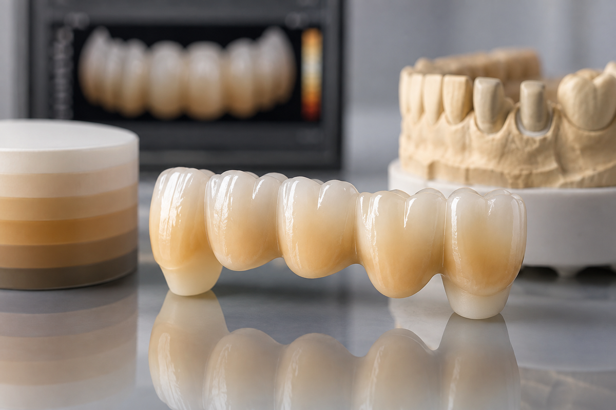
A single-unit multilayer crown is a manageable esthetic challenge. The restoration occupies one position, the gradient runs from cervical to incisal within a single milled blank, and the technician has one toolpath to align with the disc's internal zone structure. A multi-unit bridge in the same material is a fundamentally different problem. The gradient must read consistently across three, four, or five units simultaneously each unit occupying a different position in the disc, each influenced differently by the span geometry, connector placement, and milling toolpath. When it works, a well-executed ST multilayer bridge is indistinguishable from natural dentition. When it goes wrong, the gradient inconsistency is visible from across the room.
The difference between those two outcomes is not luck. It is a set of specific, controllable decisions made at the design stage, during milling setup, at sintering, and through the finishing protocol. Each decision either preserves the gradient architecture the disc manufacturer engineered into the material or undermines it. This guide covers every decision point in detail giving dental labs a technically grounded workflow for producing ST multilayer zirconia bridges that maintain their natural shade gradient consistently, case after case.
Understanding What the ST Multilayer Gradient Actually Is
Before troubleshooting or optimizing a multilayer bridge workflow, it is worth being precise about what the gradient in an ST multilayer disc consists of because vague understanding of the gradient architecture leads to vague decisions that produce inconsistent outcomes.
ST stands for super-translucent. In the context of Upcera's product range, ST multilayer discs are manufactured with a progressive gradient of yttria content and pigmentation through the depth of the disc. The cervical end of the disc contains a formulation with higher chroma, warmer undertone, and slightly reduced translucency replicating the optical character of dentin. Moving toward the incisal end, the yttria content increases, the pigmentation shifts toward cooler, less saturated values, and the translucency increases replicating the optical character of enamel.
This gradient is not a surface coating. It is not a staining applied after disc manufacture. It is a compositional gradient built into the material through the manufacturing process itself which means it can only be preserved or destroyed during the milling workflow. It cannot be corrected after sintering. A restoration milled with the gradient misaligned will exit the sintering furnace with a misaligned gradient, and no amount of staining will reconstruct the internal optical architecture that was lost at the milling stage.
This is the fundamental principle that governs every workflow decision that follows: the gradient is preserved or destroyed before sintering, not after.
Disc Orientation: The Single Most Important Setup Decision
For a single-unit crown, disc orientation errors are a recoverable problem — the technician mills a second blank and adjusts. For a multi-unit bridge, a disc orientation error wastes the entire bridge span and often a significant portion of an expensive disc. Getting orientation right before milling is not optional.
The st multilayer zirconia disc from Upcera carries a directional marking typically an engraved arrow or a color-coded edge marking that indicates which direction is gingival and which is incisal. This marking is the reference for every orientation decision in the workflow that follows. Before mounting any disc, confirm that you understand and can see the marking clearly. If the marking is ambiguous or not visible, consult the product documentation before proceeding.
Mount the disc in the milling machine chuck with the gingival direction aligned according to the manufacturer's specification. For most systems, the gingival end of the disc corresponds to the bottom of the milling chamber but confirm this for your specific mill-disc combination. A disc mounted in the correct overall orientation but 180 degrees rotated in the wrong axis will still produce a gradient-reversed bridge.
For bridge cases specifically, there is an additional orientation consideration that single-unit cases do not present: the bridge span extends across a wider portion of the disc than a single crown, and the gradient must be consistent not only from cervical to incisal in each unit but also laterally consistent across the full span. This means the bridge should be positioned so that all units share the same position in the gingival-to-incisal axis of the disc — not staggered at different heights, which would give different units access to different gradient zones.
Practical rule: in a 3-unit bridge, all three pontic and retainer units should occupy the same band of the disc in the gingival-to-incisal dimension. Their lateral position within that band is flexible. Their position in the gradient axis should be identical.
CAD Toolpath Alignment: Mapping the Design to the Disc Zones
Disc orientation sets the physical relationship between the disc and the milling chamber. CAD toolpath alignment sets the relationship between your digital design and the disc's internal gradient zones and this is where most gradient failures in bridge cases actually originate.
In exocad, 3Shape, or any CAD software with blank orientation mapping functionality, the layer-mapping tool displays a representation of the disc's gradient zones and allows the technician to position the digital restoration design within those zones before generating the toolpath. For a single crown, the standard guideline is straightforward: margin at the gingival zone, cusp tips reaching into the enamel zone. For a bridge, the same principle applies per unit, with the added requirement that the zone alignment is consistent across all units in the span.
The st pre shaded zirconia product range includes pre-shaded formulations where the shade gradient is calibrated to specific VITA shade values meaning the layer-mapping decision determines not just translucency distribution but also the specific shade zone each unit accesses. A unit whose margin falls in the body zone rather than the dentin zone will produce a different cervical shade value than its neighbors, even if the same disc is used and the milling was otherwise identical.
For bridge cases, build a standard zone mapping template in your CAD software that positions the bridge span correctly within the disc gradient for the most common bridge lengths you produce 3-unit, 4-unit, and 5-unit spans. Applying a validated template consistently is more reliable than making individual zone mapping decisions on each case.
For a deeper understanding of how zirconia grade and disc architecture interact with shade outcome across different bridge indications, the Guide to Materials & Strengths of Zirconia Dental Restorations covers the full material selection framework including when ST multilayer is and is not the appropriate grade for a given span length and occlusal load requirement.
Connector Placement and Its Effect on Gradient Continuity
Bridge connectors are structural necessities and esthetic liabilities in multilayer zirconia work. In a well-designed bridge, the connector is positioned in the interproximal space where it is visually recessive. In a poorly designed bridge, the connector cross-section interrupts the gradient zone transition between units particularly when the connector requires material from both the dentin zone and the body zone to meet minimum cross-section requirements.
Minimum connector cross-section for a 3-unit anterior ST multilayer bridge should be at a minimum 9 mm² to provide adequate structural safety margin. For posterior spans where occlusal load is higher, this rises to 12 mm² or more depending on the span and the patient's bite force profile. These are not aesthetic recommendations they are structural requirements, and reducing connector size to improve esthetic gradient continuity at the connector is a clinical mistake that risks fracture at the connector under functional load.
The practical approach to connector placement in gradient-critical bridges is to position the connector as far incisally as the esthetic zone permits keeping it out of the high-chroma dentin zone at the cervical, where gradient interruption is most visible. A connector that spans the middle and incisal thirds of the proximal surface is visually recessive and structurally adequate for most anterior spans. A connector that drops into the cervical third creates a visible shade interruption at the most visible part of the restoration.
For zirconia bridge dental cases specifically, mapping connector position in the design phase against the gradient zone visualization in your CAD software is the most reliable way to confirm that connector placement is not interrupting a zone transition before the bridge goes to the mill.
Milling Parameters: Speed and Tool Management Through Gradient Transitions
The hardness of ST multilayer zirconia varies slightly between gradient zones. The dentin zone with its higher chroma pigmentation and slightly lower yttria content is marginally denser than the incisal zone. This hardness variation is small enough to be clinically irrelevant in terms of the finished restoration but significant enough to affect milling behavior at the interlayer boundary.
In a single-unit crown, the toolpath passes through the gradient transition once per occlusal surface pass. In a bridge, the toolpath makes repeated passes through gradient transitions across the full span, and the accumulated effect of those transitions on bur wear is more significant than it appears on a per-pass basis.
Two practical milling adjustments preserve surface quality at gradient transitions in bridge cases:
Reduce feed rate by 10–15% at the gradient transition zone.
In most CAD/CAM software, you can identify the approximate position of the gradient transition in the disc and set a feed rate reduction flag at that depth. The slightly reduced feed rate preserves surface integrity at the transition point.
Replace milling burs more frequently for long-span bridges.
A bur that is 70% worn is adequate for a single-unit crown. The same bur on a 4-unit bridge will produce progressively rougher surface quality across the span as wear accumulates during the longer milling cycle. For st multilayer dental blocks cases involving spans of three or more units, fresh burs at the start of each bridge milling job are the correct protocol.
Sintering: The Protocol That Determines Whether the Gradient Survives
The optical properties of ST multilayer zirconia and particularly the gradient's translucency distribution are determined during sintering. The controlled grain growth that produces translucency in the incisal zone depends on a specific sintering temperature profile: a slow, controlled ramp rate and a precise peak hold temperature and duration.
For ST multilayer zirconia, the sintering profile should specify:
Ramp rate: ≤5°C per minute from 900°C to peak temperature
Peak temperature: 1480–1520°C depending on the specific product (always confirm with the manufacturer's published profile)
Hold time at peak: 2 hours minimum for most formulations
Cool-down rate: ≤10°C per minute from peak to 900°C rapid cool-down causes thermal stress that can produce micro-cracking at gradient zone boundaries in bridge spans
For bridge cases specifically, the increased mass of a multi-unit span compared to a single crown means the sintering furnace must distribute heat evenly across a longer object. Bridge supports are critical here use manufacturer-recommended zirconia pins or a support tray that provides even support under all units without contact on occlusal surfaces or margins. Uneven support creates differential stress during sintering that produces warping, and warped bridges show gradient inconsistency across units because different parts of the restoration experienced different thermal histories.
Do not run accelerated sintering cycles on ST multilayer bridge cases. The time savings of an accelerated cycle on a single crown are marginal. The risk on a multi-unit bridge gradient degradation, micro-cracking at connectors, and reduced translucency in the incisal zones is disproportionate to that saving. Standard sintering profiles are non-negotiable for gradient-critical multilayer bridge work.
Post-Sintering Evaluation: Checking Gradient Consistency Before Delivery
After sintering, evaluate the bridge gradient under three different light sources before proceeding to glazing or delivery: standard fluorescent lab lighting, natural daylight, and incandescent light. A gradient that appears consistent under fluorescent light may show visible zone discontinuities under natural daylight particularly at the connector areas and at the transitions between adjacent units.
Specifically check for:
Visible chroma banding — a distinct line between the dentin and body zones that should read as a smooth transition. Banding indicates a zone alignment error in the toolpath that placed two units at different positions in the gradient axis.
Lateral shade inconsistency between units — one retainer appearing warmer or darker than the pontic or the opposing retainer. This indicates the bridge was positioned at an angle to the gradient axis during milling, so different units accessed different shade values within the same gradient zone.
Connector opacity — a connector area that appears more opaque than adjacent tooth surfaces. This is usually a design issue the connector cross-section extends into a zone with lower translucency, or the connector wall thickness is sufficient to block light transmission at that point.
If any of these issues are present, the bridge requires remilling. Post-sintering staining can add characterization and surface color, but it cannot reconstruct an internal gradient that was misaligned before sintering. Attempting to correct gradient failures with heavy staining produces restorations that look painted rather than natural, and the stain is less stable long-term than the internal gradient.
For US dental labs evaluating whether to buy st multilayer zirconia online for bridge production, ZirconiaGuys stocks the full ST multilayer range from Upcera from US inventory including multiple thicknesses for different bridge span requirements with consistent batch documentation and same-day shipping on in-stock items.
Finishing Protocol: Glazing That Enhances Rather Than Masks
The finishing protocol for an ST multilayer bridge should enhance the natural gradient, not attempt to compensate for it. If the workflow has been executed correctly through milling and sintering, the gradient is present in the material and requires only surface refinement.
Glaze application: Apply a thin, even glaze layer across all units using a brush. Avoid pooling at connector areas, which creates optically dense zones that interrupt gradient continuity at exactly the points where consistency matters most. Fire the glaze at the manufacturer's specified temperature typically 750–780°C for most compatible glazes with a hold time of 1–2 minutes.
Stain application: For standard pre-shaded ST multilayer bridges in A–D shade range, staining should be minimal or absent. If the referring clinician requires specific shade characterization a slightly higher A2 chroma at the cervical of one retainer to match an adjacent natural tooth, for example apply a targeted cervical stain to that unit only. Do not apply blanket staining across all units of a bridge that does not require it.
The st multilayer zirconia discs are calibrated to deliver consistent VITA shade values across the gradient with minimal finishing intervention on standard cases. The workflow investment is at the design and milling stage not at the staining bench. Labs that find themselves routinely applying heavy staining to correct ST multilayer bridge shade outcomes are usually dealing with a disc orientation or zone alignment problem upstream, not a finishing problem.
Maintaining the natural gradient across an ST multilayer zirconia bridge dental case is not a matter of technique at the finishing bench it is a matter of precision at every stage upstream. Correct disc orientation before mounting. Accurate zone mapping in the CAD toolpath. Thoughtful connector placement that respects both structural requirements and gradient zone boundaries. Controlled sintering profiles that allow the material's optical properties to develop correctly. Post-sintering evaluation under multiple light sources before delivery.
Each of these steps is individually straightforward. Executed consistently together, they produce multi-unit bridges that pass shade evaluation without heavy staining correction, deliver predictable esthetic outcomes that referring dentists can specify with confidence, and demonstrate the level of material control that distinguishes a technically capable dental laboratory from one producing acceptable but unpredictable results. Stocking dental zirconia discs and zirconia dental blanks from a consistent, well-documented source is the last link in that chain because gradient consistency across batches begins with material consistency from the supplier. Zirconia blank and zirconia blocks dental procurement from a reliable US-stocked source ensures the material you validated your protocol on is the same material in every subsequent production run.


